Introduction to the Integrated Monitoring System of Building Equipment
"Smart Chiller & AHU Control"
Project Overview
The project is located in plot 0804, Jiangqiao Town, Jiading District, Shanghai. The total construction area is 84668.63 m2, including 58,305.83 m2 above ground and 354,625.8 m2 underground. The main building has two to eleven floors, with a maximum height of 43.2m. The second underground level is a car parking garage, while the first underground level is for R&D facilities, car parking garages, and mechanical and electrical equipment rooms; the basement mezzanine is a non-motorized garage. Buildings 1 to 7 are all R&D offices and supporting facilities, building 8 is a garbage room, and building 9 is a duty room.
Overview of HVAC Design
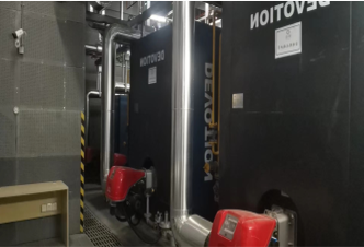
Buildings 1 to 5, and R&D supporting facilities (1F and 2F) in Building 6, with centralized air conditioning cooling and heat sources on the basement level. The cold and heat sources are equipped with chillers and gas vacuum boilers.
The duty room and guard room of the R&D office (3F~top floor), boiler room, substation, and refrigeration room in Building 6 all use split type air conditioning units.
Building 7 (one underground floor and two above ground floors) is equipped with separate cooling and heating sources, using a vortex type air-cooled heat pump unit.
The refrigeration room, substation, network room, garbage room, property office, etc. adopt a multiline system.
The top floors of buildings 1 to 5, 2f, are equipped with vav variable air volume air conditioning systems.
The lobby on the first floor of buildings 1 to 6, the cafeteria on the first floor of buildings 4, 5, and 6, as well as the r&d supporting facilities (cafeteria) and exhibition halls on the underground floor, adopt a constant air volume all air system.
The R&D conference room on the first floor of buildings 1-4 adopts an air water air conditioning system with fresh air and fan coil units.
Floor duct type fan coil units are installed along the outer edge of the first and second floors of building 7. the basement of building 7 adopts an air water air conditioning system with fresh air and fan coil units.
The other R&D facilities on the basement level, including the elevator hall, r&d facilities (fitness), changing rooms, bathrooms, etc., are all designed with fan coil units and fresh air systems
Overview of HVAC Design
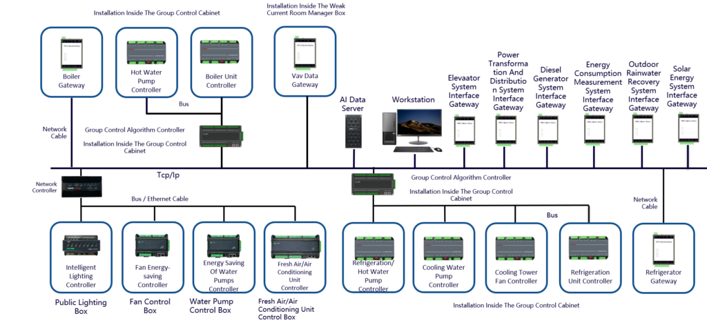
System Architecture
Monitoring Content
System Architecture
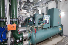
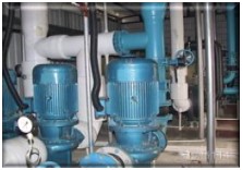
Cold Source Group Control System
Heat Source Group Control System
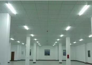
Public Lightning System
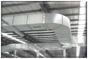
Air Supply and Eshaust System
Water Supply and Drainage System
Air Conditioning System (Including VAV End)
And Other Electromechanical Systems
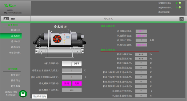
Features Cold Source System
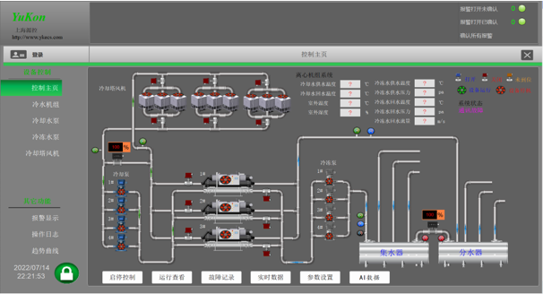
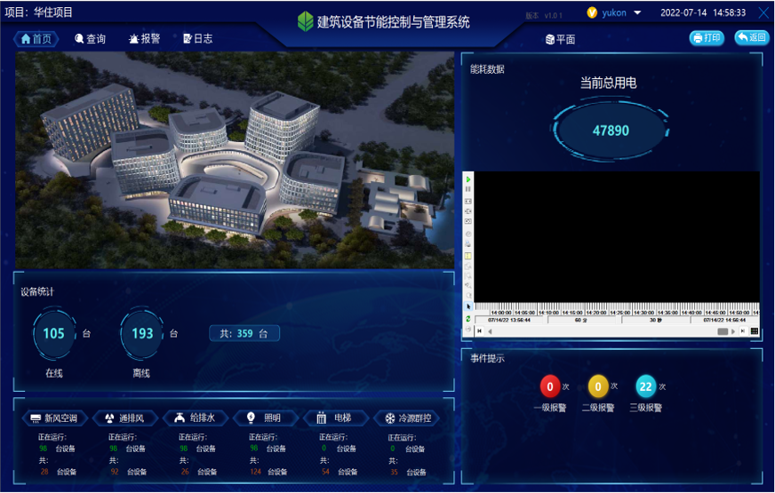
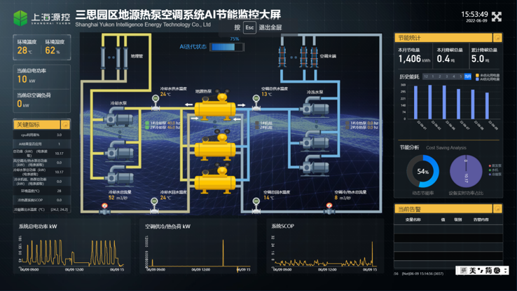
Human-Computer Interaction Interface
System monitoring
Monitor internal parameters of the refrigeration unit through protocol interfaces;
Monitor the manual/automatic status, operating status, fault status, and frequency feedback of chiller units, refrigeration pumps, cooling towers;
Detect the accumulated operating time and scheduled maintenance prompts of chillers, refrigeration pumps, cooling pumps, and cooling towers;
Monitor the energy consumption of each equipment during operation;
Monitor the water flow status of the chilled water pump and cooling water pump;
Monitor the supply and return water temperature, pressure, and flow rate of the chilled water main, as well as the water pressure difference between the supply and return, and the instantaneous opening of the electric balance valve;
Monitor the temperature of the cooling water supply and return water.
Detection of outdoor temperature and humidity monitoring.
System control
Remote control system equipment start and stop;
Interlock the start stop equipment in the correct order (butterfly valves open accordingly);
Automatically control the addition and subtraction of the unit based on its operating load;
According to the pressure difference between the chilled water supply and return main pipes, PID adjusts the opening of the bypass valve of the collector to maintain a stable flow rate of chilled water supply;
Balanced wear and tear, prioritize starting the unit with the shortest cumulative operating time, and when shutdown is required, close the unit with the longest cumulative operating time
Human-Computer Interaction Interface
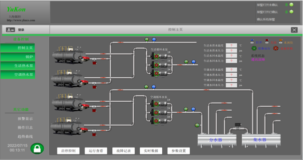
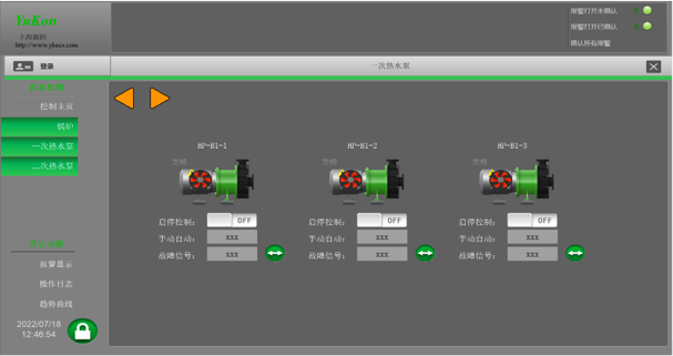
Features Heat Source System
Human-Computer Interaction Interface
System monitoring
Monitor internal parameters of the boiler through protocol interfaces;
Monitor the manual/automatic status, operating status, fault status, and frequency feedback of boiler units, air conditioning circulating pumps, and domestic circulating pumps;
Detect the cumulative operating time and scheduled maintenance prompts of boiler units, air conditioning circulating pumps, and domestic circulating pumps;
Monitor the temperature and pressure status of the supply and return water in the domestic water main;
Monitor the temperature and pressure status of the supply and return water in the air conditioning water main, as well as the instantaneous opening of the electric balance valve;
Detection of outdoor temperature and humidity monitoring.
System control
Chain control of hot water circulation pump and boiler;
According to the temperature of the circulating water supply and return main pipes, PID adjusts the operating frequency of the circulating pump;
According to the pressure difference between the main supply and return pipes of the circulating water, PID adjusts the opening of the bypass valve of the water collector to maintain a stable supply pressure of the circulating water;
Balanced wear and tear, guiding priority to start the unit with the shortest cumulative operating time. When shutdown is required, priority should be given to shut down the unit with the longest cumulative operating time.
Human-Computer Interaction Interface
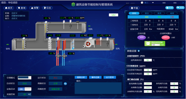
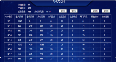
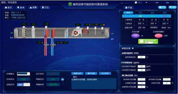
Features Air Conditioning System
Human-Computer Interaction Interface
System monitoring
Monitor the manual/automatic status, operating status, and fault status of the fan;
Monitor the cumulative operating time of the fan and issue maintenance prompt signals at regular intervals;
Monitor the clogging status of the filter and remind operators to clean it in a timely manner;
Monitor the temperature and humidity of the supply and return air.
Monitor the opening of the new return air valve and water valve.
Monitor indoor VAV, etc.
System control
Timed control: Control the start and stop of the unit according to a pre arranged time program;
Based on the deviation between the return air temperature and the set value, adjust the opening of the electric water valve through PID operation to maintain the indoor temperature within the set range;
Adjust the new return air ratio through PID operation based on the deviation between the return air CO2 and the set value;
According to the deviation between the return air humidity and the set value, automatically control the start and stop of the humidification valve to maintain indoor humidity within the set range.
According to the temperature of the supply and return air, adjust the opening ratio of the electric air valves for fresh air and return air using enthalpy control method to maintain the system operating at the optimal fresh air/return air ratio;
Human-Computer Interaction Interface
The fresh air valve, fan, and water valve are interlocked and controlled. When the fan is stopped, the fresh air valve and water valve are automatically closed. Before the fan starts, the air valve is automatically opened with a delay.
Anti freeze switch interlocking control protection to prevent damage to the coil in winter.
Set the static pressure value based on the end VAV opening, and adjust the operating frequency of the unit according to the set static pressure.
Features Fresh Air System
Human-Computer Interaction Interface
System monitoring
Monitor the manual/automatic status, operating status, and fault status of the fan;
Monitor the cumulative operating time of the fan and issue maintenance prompt signals at regular intervals;
Monitor the clogging status of the filter and remind operators to clean it in a timely manner;
Monitor the temperature and humidity of the air supply.
Monitor the opening of fresh air valves and water valves.
System control
Timed control: Control the start and stop of the unit according to a pre arranged time program;
According to the deviation between the air supply temperature and the set value, adjust the opening of the electric water valve through PID operation to maintain the air supply temperature within the set range;
According to the deviation between the supply air humidity and the set value, automatically control the start and stop of the humidification valve to maintain the supply air humidity within the set range.
The fresh air valve, fan, and water valve are interlocked and controlled. When the fan is stopped, the fresh air valve and water valve are automatically closed. Before the fan starts, the air valve is automatically opened.
Anti freeze switch interlocking control protection to prevent damage to the coil in winter.
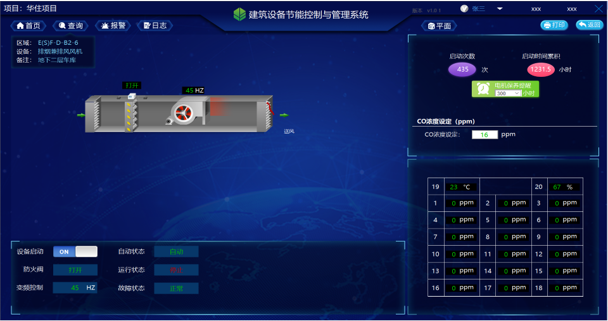
Features Air Supply & Exhaust System
Human-Computer Interaction Interface
System monitoring
Fan manual/automatic status, operating status, and fault status;
Fan fire damper status;
Accumulated operating time of the fan, issuing maintenance prompt signals at regular intervals;
CO detection concentration in the control area of the underground garage fan.
System control
Timed control: Control the start and stop of the fan according to a pre arranged time program;
Chain control based on CO concentration.
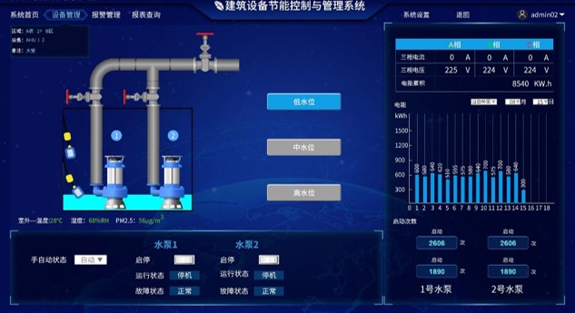
Features Water Supply & Drainage System
Human-Computer Interaction Interface
Add Your Heading Text Here
Pump manual/automatic status, operating status, and fault status;
Accumulated running time of the water pump, issuing maintenance prompt signals at regular intervals;
Monitoring of high liquid level, low liquid level, and overflow liquid level in the collection well;
Add Your Heading Text Here
Manual and automatic start stop control of water pumps;
Control the start stop and rotation of the water pump based on the high, low, and overflow level signals of the collection well;
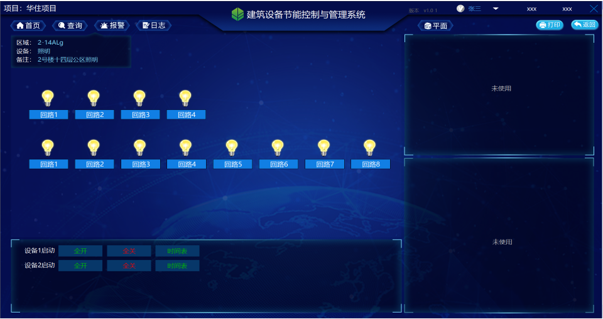
Feature Lighting System
Human computer interaction interface
System Monitoring
Remote control of the circuit.
Timing control.
Scene control.
Group Control System
Group Control Algorithm Controller ECS-7000MZK
The controller is equipped with intelligent fuzzy control algorithm and expected algorithm and optimization algorithm for energy efficiency optimization management, which can achieve real-time tracking and feedback of the operating parameters of the group control system, intelligently adjust the refrigerant flow according to the load demand, ensure that the host is in the best operating condition under any load conditions, and maintain a high COP of the air conditioning host at all times. Timing control.
Real time data transmission and analysis can be carried out through the bus with other dedicated controllers such as chillers, pumps, cooling towers, butterfly valves, etc. The calculation of the entire energy-saving software of the air conditioning system can be adjusted in real time to achieve overall energy-saving control of the air conditioning system.
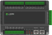
Group control dedicated energy-saving controller ECS-7000MLS/D/Q/T/R
The controller interacts with the main controller of the group control algorithm in real-time through the CAN bus, and receives control instructions sent by the algorithm controller to achieve overall optimal energy-saving control.
The controller automatically controls a single refrigeration pump/cooling pump/hot water pump, cooling tower, butterfly valve interlocking control, frequency conversion control, single equipment status display and fault alarm, optimal equipment combination configuration, and automatic balancing wear and tear functions.
Group Control System
Gateway ECS-7000WG
Devices using RS-232/485 interface protocol are connected to TCP switches to achieve communication between RS-232/485 devices and the upper computer management system
End of line equipment
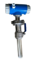
Water pipe temperature sensor
Water pipe temperature sensor
Water pipe flow sensor
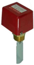
Water flow switch
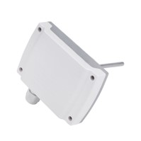
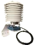
Outdoor temperature and humidity sensors
Air Conditioning System
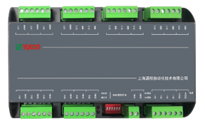
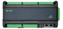
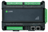
Air conditioning unit energy-saving controller ECS-7000MKT
The controller adopts a dual Ethernet communication interface, which enables Ethernet daisy chain topology networking between controllers, facilitating flexible networking on site.
The network communication method supports the BACnet-IP communication protocol.
The controller is equipped with an independent CPU as the core, which can expand LCD display, button input, RS485 communication, electrical parameter acquisition, AI, DI, DO, AO and other input sampling and output control circuits.
Controller I/O quantity: 6 DIs, 11 UIs, 3 DOs, 2 UOs, and 4 AOs. It can support multiple input and output forms of conversion through pins and software settings, and can expand the IO port of the main module through expansion modules.
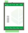
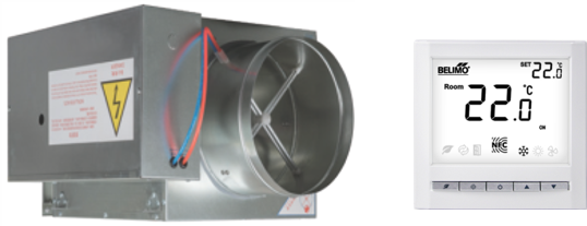
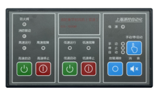
Cabinet display operation screen ECS-LCD5
The local operation panel matched with the energy-saving controller of the ECS-7000MKT air conditioning unit has the RS485/MODBUS bus communication function, which is mainly used for local monitoring and can replace the traditional cabinet buttons, indicators and other anime devices.
VAV equipment
According to changes in indoor load or indoor required parameters, maintain a constant air supply temperature, automatically adjust the air supply volume of the air conditioning system, so as to achieve the required indoor parameters for a fully air conditioning system.
Air duct temperature and humidity sensor
Air duct CO2 sensor
Differential pressure switch
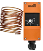
freeze protection
Air duct static pressure sensor
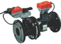
Air valve actuator
Water valve actuator
Air Supply & Exhaust System
Energy saving controller for water pump ECS-7000MB
The controller adopts a dual Ethernet communication interface, which enables Ethernet daisy chain topology networking between controllers, facilitating flexible networking on site.
The network communication method supports the BACnet-IP communication protocol.
The controller is equipped with an independent CPU as the core, which can expand LCD display, button input, RS485 communication, electrical parameter acquisition, AI, DI, DO, AO and other input sampling and output control circuits.
Controller I/O quantity: 9 UI, 3 DO, 2 UO, can support multiple input and output forms of conversion through pins and software settings, and can expand the IO port of the main module through expansion modules.
Cabinet display operation screen ECS-LCD4
The embedded operation panel supporting the ECS-7000MB water pump energy-saving controller has the RS485/MODBUS bus communication function, which is mainly used for local monitoring of various water supply and drainage pumps, and can replace the traditional cabinet buttons, indicators and other anime devices.
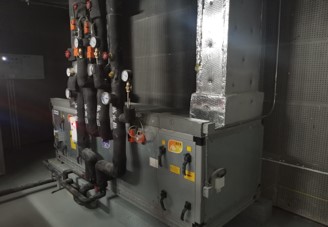
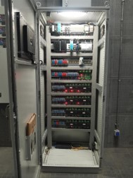
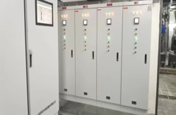
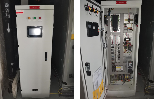
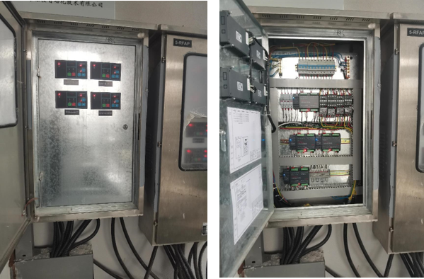
Cold source system control cabinet
Heat source system control cabinet
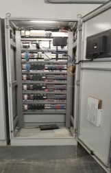
Water pump control box
Air conditioning control cabinet
Fan control cabinet
System Software
The human-computer interaction platform software is a complete set of software and hardware solutions applied to visualization, control, management, and data analysis in industries, buildings, infrastructure, and public construction projects. A software solution that includes all monitoring and control functions, including databases, object-oriented flat graphics, alerts, recipes.
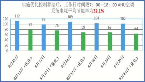
Application of AI Algorithm
The energy consumption of equipment related to the cold source group control system accounts for about 30-50% of the total energy consumption of the building, and is an important link that cannot be ignored in building energy conservation. Most of the existing cold machine group control systems are program control systems, which can automatically start and stop, interlock, and protect the cold unit according to the logic settings of engineers. However, due to hardware and software limitations, it is difficult to consider more factors that affect system efficiency (such as the trend of changes in the cooling/heating load of the building in the future), making it difficult to maintain a high level of operational efficiency for the refrigeration station. By utilizing the AI based energy-saving control algorithm for central air conditioning, an overall optimal control solution can be achieved.
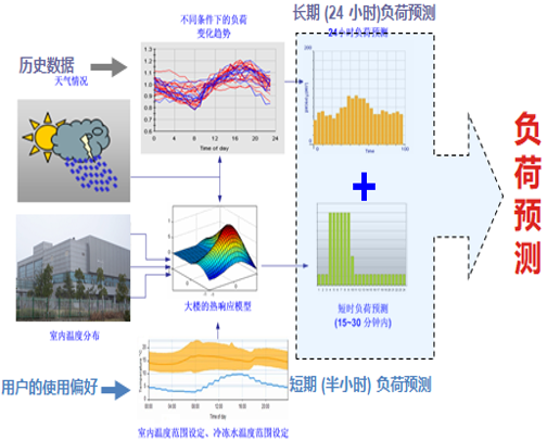
Application of AI Algorithm
Cold Source Group Control System-Energy-saving Management Flowchart
Cold source machine room group control system Energy saving strategy: An optimized energy-saving control platform for central air conditioning/HVAC based on AI artificial intelligence. Application of core AI artificial intelligence algorithms in computer room group control systems: Absolute optimization of all components of the refrigeration system; The global intelligent algorithm jointly solves the minimum total energy consumption of the system; Under the premise of the lowest total energy consumption of the group, actively control each component instead of traditional passive feedback control; Technologies adopted: intelligent air conditioning load prediction technology, indoor thermal comfort intelligent identification technology, fuzzy optimization variable static pressure control technology, etc.
error: Content is protected !!
Scroll to Top
Any questions related to HVAC (Heating Ventilation and Air-Conditioning)?